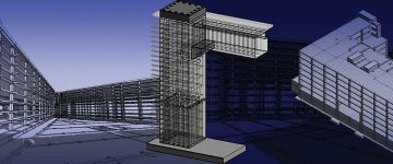
- Modern architecture, fabrication, and construction complexities, combined with condensed timelines drive the shift from legacy 2D to BIM for Precast Structural Engineering.
- Revit for concrete design enables seamless integration of 3D modeling, drawings, and material estimation/quantity takeoff to enhance efficiency for the entire project lifecycle.
- Precast concrete structures in Revit for large projects benefit from splitting Revit 3D models using collaborative approaches and parametric families to streamline design and coordination.
In structural engineering, precision and speed are extremely important. Relying on 2D design for cast-in-place and precast concrete structures is no longer enough for modern construction design projects. Without the use of Revit or similar advanced tools for designing precast concrete structures, engineers face fragmented workflows, where drawings and material estimates stay isolated, resulting in mistakes, revisions and project holdups. The lack of a unified platform hampers collaboration and coordination among teams, further slowing project progress.
Revit’s use in concrete structural detailing and design offers a solid foundation for engineers and precast manufacturers to overcome these hurdles. By examining how Revit smoothly integrates 3D modeling, drawing creation, and material quantification, we reveal its potential to streamline workflows and improve project results. This enables the visualization of complex designs, clash detection, and material optimization, leading to increased efficiency and cost savings.
Table of Contents
- Precast concrete structures in Revit
- Proven processes to organize a design cycle in Revit
- Top 3 ways of developing construction documentation in Revit
- Exploring various methods of designing Cast-in-Place structures in Revit
- Navigating ways to design precast structures in Revit
- The need to switch from 2D to 3D
- Heading to a conclusion
For industry professionals in cast-in-place concrete, in this article, we explore 3D reinforcement modeling techniques and the use of parametric Revit families for prefabricated members. Using Revit, engineers can boost design accuracy, enhance communication with contractors, and enable seamless construction. The focus on Revit best practices for structural engineering and cast-in-place is in line with the industry’s pursuit of data-driven decisions, optimized workflows, and collaboration.
Precast concrete structures in Revit
Currently, precast concrete projects rely heavily on AutoCAD for 2D shop drawing creation and detailing. This approach creates a gap between design and fabrication, increasing the risk of errors and on-site reworks. The lack of 3D visualization makes interference detection difficult, potentially leading to cost overruns and delays during construction.
Proven processes to organize a design cycle in Revit.
Revit has transformed precast design by centralizing the complete process. It has enabled the creation of smart 3D models, automated shop drawing creation and interdisciplinary clash detection to ensure accuracy and error reduction for the entire precast workflow.
Design Development [3D – LOD 200 + 2D]
At this stage, Revit supports engineers in refining the concept model into an analytical model to perform structural calculations. Moreover, basic structural elements can take shape in 3D, while 2D annotations within Revit replace the need for different AutoCAD drawings that foster a unified BIM environment.
![Design Development [3D – LOD 200 + 2D]](https://www.hitechdigital.com/wp-content/uploads/2024/11/design-development.jpg) Source: https://www.autodesk.com/
Source: https://www.autodesk.com/
Construction Documentation and Shop Drawings [3D – LOD 350]
In this phase, the 3D model evolves to LOD 350, which incorporates connections and reinforcement. This fosters precise quantity takeoffs for steel and concrete, while automated drawing extraction ensures consistency between the 3D model and documentation, which streamlines coordination and reduces errors. This improves the quality of the drawing set and the complete project.
![Construction Documentation and Shop Drawings [3D – LOD 350]](https://www.hitechdigital.com/wp-content/uploads/2024/11/construction-documentation-shop-drawings.jpg) Source: https://www.autodesk.com/
Source: https://www.autodesk.com/
Construction Support [3D – LOD 450]
The benefits of Revit for concrete contractors are many. The final model at LOD 450 is a valuable asset during construction. It supports site planning, material procurement and project progress tracking. Detailed representations allow for clash detection and resolution before on-site work begins, leading to mitigated issues and delays.
![Construction Support [3D – LOD 450]](https://www.hitechdigital.com/wp-content/uploads/2024/11/construction-support.jpg) Source: https://www.autodesk.com/
Source: https://www.autodesk.com/
UAE Residential Project Achieves Seamless Construction with 5mm Clash-Coordinated 3D Precast Model
A precast manufacturer from the UAE reached out to HitechDigital for a large-scale precast project that involved 15,000 precast structural elements. Traditional methods are error prone and time consuming. They also led to material waste and increased costs. The client partnered with HitechDigital to build a coordinated 3D BIM precast model at LOD 450 with a precision of 2 mm–5 mm.
Rebar shop drawings of concrete elements and Bar Bending Schedules (BBS), along with accurate quantity estimates and element IDs, were extracted. Read the complete case study to understand how the final deliverables supported the client –
- Save costs with accurate procurement using 3D models for M60 concrete grade
- With improved quality of precast elements
- Achieve quick TAT of BIM deliverables that enabled expedited on-site building erection
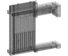 Column Beam Slab Junction
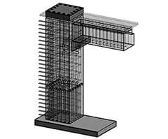 Column Beam Junction
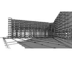 Building Perspective view
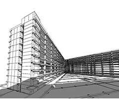 Building Image
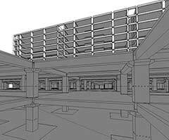 Building Internal View
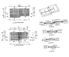 Staircase Reinforcement
Experience faster builds, fewer errors, and lower costs with our precast expertise.
Gain a competitive edge with faster and more efficient construction.
Top 3 ways of developing construction documentation in Revit
Free-standing structures and buildings with less than 53,000 square feet in area.
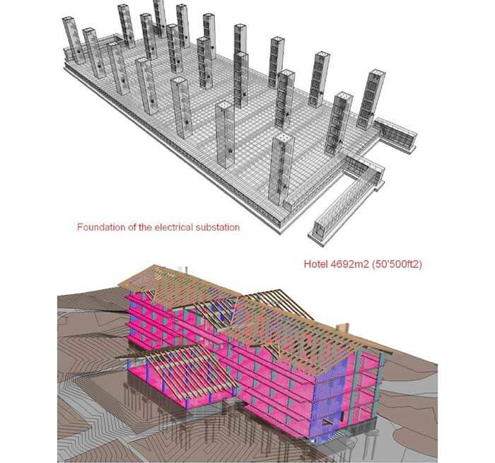
For smaller buildings and freestanding structures under 53,000 square feet, Revit provides a streamlined approach to construction documentation. The primary technique involves creating the complete project within a unified Revit file. This is helpful for projects without standardized elements and extensive repetition. A centralized platform for modeling, annotation and the generation of drawings facilitates a cohesive workflow.
As projects develop in complexity, it is beneficial to utilize Revit’s linking capabilities. This supports breaking down the 3D model into smaller and more manageable files to improve performance and enable various teams to work on various building sections.
Finally, for projects with repetitive components, generating different Revit files for every structural member can accelerate drawing production. This technique facilitates the reuse of annotations and views to lower effort duplication and ensure consistency across similar elements.
 Source: https://www.autodesk.com/
Buildings with 53,000 – 160,000 in area.
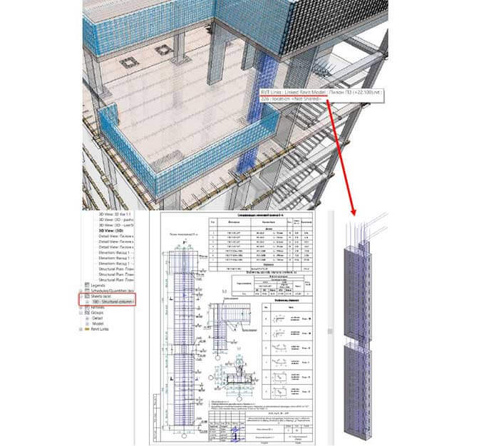
For buildings within the range of 53,000 to 160,000, Revit’s construction documentation focuses on collaboration and efficiency. A common approach includes developing and detailing every structural member in the Revit file itself. This fosters focused work within a small team. It also supports the quick copying and modification of components across multiple building sections to promote time savings and consistency.
Moreover, if the project includes standardized components or requires a greater level of collaboration, linking multiple Revit files is vital. This supports various team members in working concurrently on multiple building areas while maintaining a single coordination model.
Finally, if the project requires in-depth annotation and detailing, using Revit’s advanced drafting tools within the 3D model is preferable. This ensures the referencing and association between 2D documentation and the 3D model to lower errors and streamline revisions.
 Source: https://www.autodesk.com/
Buildings larger than 160,000 in area.
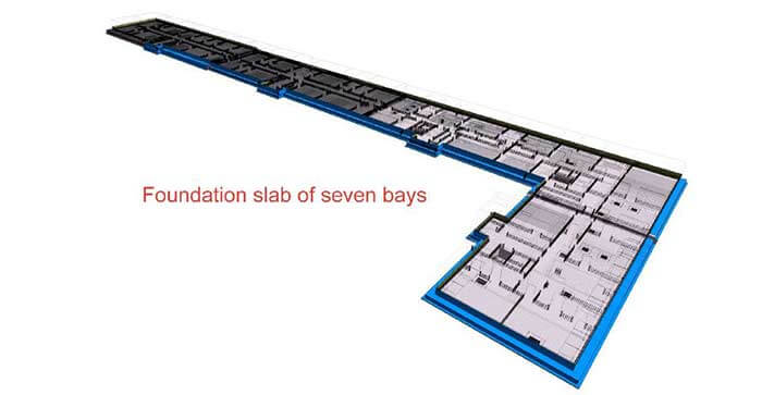
For expansive projects exceeding 160,000 square feet, Revit’s construction documentation capacity adopts a flow design process. This includes dividing the building design into various files based on floor levels and structural types. This enables designers to work concurrently using Revit collaboration tools. This accelerates design, facilitates seamless coordination, and ensures that everyone is working on a single BIM model.
Another technique involves using Revit’s worksets and linking features. Strategic linking of various Revit models containing multiple building systems or structural components helps maintain a cohesive framework to manage file size and enhance performance. Worksets deliver an additional layer of control that allows team members to isolate and change specific model parts without affecting other people’s work.
Additionally, for large projects with repetitive members, the use of standardized families and templates is vital. This promotes consistency, reduces modeling time and simplifies drawing creation. Predefined annotation styles and views improve efficiency and ensure uniformity across project documentation.
 Source: https://www.autodesk.com/
Exploring various methods of designing Cast-in-Place structures in Revit
Utilizing standardized Revit tools
Using Revit’s built-in structural rebar tools provides a strong foundation for cast-in-place concrete design. Engineers can model reinforcement bars, meshes and stirrups directly within the 3D model using placement features and automatic bar bending. This technique streamlines design and ensures the precise visualization of reinforcement details.
Working with “IFC-rebar” Families.
For complex or repetitive reinforcement members like mats and cages, “IFC-rebar” families provide greater flexibility. These parametric families, integrated within the Revit project, allow for effective modeling and changes within prefabricated reinforcement assemblies to save time and reduce errors.
Combined technique of using IFC and Common files.
This approach involves a combination of two methods. Standard Revit tools can handle on-site reinforcement, while “IFC-rebar” families can manage prefabricated members. This hybrid technique improves efficiency, utilizes the capabilities of each method, and ensures a precise representation of cast-in-place concrete.
Achieve precision precast, on time and on budget.
Streamline your projects with enhanced visualization and eco-friendly design solutions.
Navigating ways to design precast structures in Revit
Assemble 3D models and installation drawings.
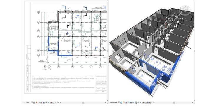
In Revit, precast design starts with generating accurate and intelligent 3D families for every concrete unit that focuses on geometry and connections but not reinforcement. These units are assembled into a unified 3D model that aids visualization and clash detection. Installation drawings are extracted directly from the 3D model, complete with schedules and parametric connection details.
 Source: https://www.autodesk.com/
Build a set of shop drawings.
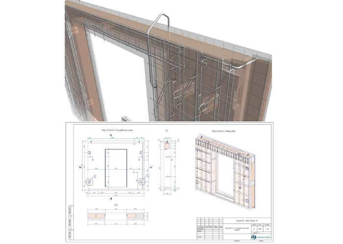
Creating shop drawings depends on the capabilities of the manufacturer. If 3D models are needed, Revit provides accurate and detailed reinforcement within unit families, generating fabrication-ready drawings. Furthermore, for manufacturers with set 2D workflows, 3D unit families are shared, allowing them to generate shop drawings using their existing systems.
 Source: https://www.autodesk.com/
The need to switch from 2D to 3D
The transition from 2D to 3D for cast-in-place and precast structural engineering is vital to stay competitive within the precast manufacturing industry. 3D modeling tools such as Revit offer powerful visualization, clash detection, and coordination capabilities that lower rework and errors. This translates to accelerated project delivery, cost savings and greater client satisfaction. While the initial learning curve and investment may be challenging, the long-term advantages of accuracy and improved efficiency make the switch to 3D a strategic necessity.
Heading to a conclusion
Revit has proven to be an unparalleled tool in structural engineering, notably for precast concrete design and cast-in-place concrete. It supports engineers in overcoming the limitations of 2D workflows, providing seamless collaboration, greater design accuracy and optimized project results.
Embracing Revit’s capabilities and utilizing best practices will help the industry set the path for efficient, sustainable and innovative construction.
Maximize your project’s potential with our value engineering and optimized solutions.
Reduce risks and elevate project outcomes with optimized Revit workflows.


