- Converting a solid part to a sheet metal part in SolidWorks requires the use of the “Convert to Sheet Metal” tool, accessible under the Sheet Metal tab or Insert menu.
- Key steps in the conversion process include selecting a fixed face, specifying sheet metal thickness and bend radius, defining bend edges and setting rip edges.
- Finalizing the part involves validating the design by flattening the model, inspecting for errors and verifying that all elements adhere to manufacturing specifications.
Table of Contents
To convert a solid part to sheet metal in SolidWorks, you need to utilize the Convert to Sheet Metal tool, which can be accessed through the sheet metal tab in SolidWorks or the Insert menu.
You first need to select an appropriate solid part with uniform thickness and perpendicular walls. Then, you’ll need to define sheet metal parameters, such as material thickness and bend radius. The conversion process also involves selecting a fixed face as a reference and defining bend edges.
After this, to properly convert the solid model to sheet metal, you need to validate the converted design using the flatten tool for manufacturability.
Here, we discuss the important processes before, during and after converting a solid part to sheet metal design in SolidWorks to help you create manufacturable components that maintain design intent while meeting production requirements.
Benefits of converting solid models to sheet metal designs in SolidWorks
Converting solid models to sheet metal design in SolidWorks simplifies design process through precise representation of sheet metal characteristics and facilitates efficient material usage. This streamlines manufacturing, reduces waste, and optimizes design accuracy.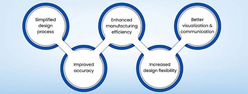
Important processes to consider before you convert solid part to sheet metal part
Before going into the process, it’s essential to understand the key considerations and preparations necessary prior to converting a solid part to a sheet metal part.
Accessing the convert to sheet metal tool
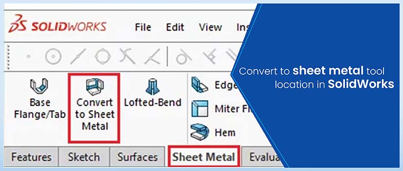
To access the Convert to Sheet Metal tool, you’ll find it under the Sheet Metal tab in the Command Manager. If the tab isn’t visible, right-click any Command Manager tab and select it. Alternatively, you can find it through the Insert ⟩ Sheet Metal ⟩ Convert to Sheet Metal menu path.
When launching the tool, you’ll need to specify a fixed face (typically the largest face parallel to the Top plane) and set the initial sheet thickness parameters in the Property Manager. The Property Manager controls the conversion parameters.
Before starting the SolidWorks sheet metal conversion, verify that you’ve selected a compatible solid part that meets sheet metal design principles, featuring mainly perpendicular walls and consistent thickness throughout the model.
Assessing solid part suitability for conversion
When assessing a solid part for sheet metal conversion, focus your evaluation on specific geometric and design elements. Begin by confirming that the model has uniform thickness throughout, a critical aspect for accurate sheet metal representation. If you find deviations, understand that rebuilding or shelling operations might be necessary.
Next, examine the part’s faces. Highly contoured or doubly curved surfaces can be difficult to unfold and may require special attention during the conversion process.
Evaluate the part’s overall design and how well it aligns with typical sheet metal features. Identify planar or nearly planar surfaces suitable for bend creation. Remember that edges need to be bendable; sharp corners or complex profiles often require design modifications to ensure successful conversion.
Be mindful of excessive geometric complexity. Numerous small features or intersecting bends complicate the conversion process. Anticipate potential relief cuts in areas with high bend stress or tight radii to prevent stress cracking and ensure formability.
Imported geometry often presents unique challenges. Carefully identify potential rip locations, particularly where the original solid model might have been joined.
Struggling with CAD models? Let us transform them into sheet metal.
Rely on our SolidWorks expertise for flawless design conversions.
Steps to convert solid part to sheet metal part in SolidWorks
The following are the essential steps for a seamless conversion process in SolidWorks, ensuring accuracy and efficiency in your sheet metal projects.
Using the thickness settings
When converting, you’ll need to specify the sheet metal thickness in SolidWorks using the Property Manager, which directly affects the part’s manufacturability and structural integrity.
Specify your desired thickness values. You can input these manually or, to ensure they align with your manufacturing processes, leverage gauge tables. The “Use gauge table” option links your model to predefined sheet metal parameters.
These tables standardize critical aspects of your design, such as material thickness, bend radius and the bend calculation method. This ensures consistency with established manufacturing standards. Select the appropriate gauge table from the dropdown menu or browse your system to locate a custom table.
You can override individual parameters within the table. This provides the flexibility needed to accommodate unique design requirements. Effective gauge table management streamlines your design intent and helps guarantee a smooth transition to manufacturing.
Specifying default bend radius
To set the default bend radius, you’ll need to locate the bend parameters section in the Property Manager. Here, you can input your desired bend radius value, which should align with your manufacturing capabilities and material specifications.
If you’re using a gauge table, you’ll find predefined bend radius values that correspond to standard material thicknesses. You can either select these preset values or customize them based on your specific requirements.
Selecting the fixed face
The fixed face acts as the base reference for all subsequent bends and features in your sheet metal part.
To select the fixed face, you’ll need to choose the largest face that’s parallel to your desired reference plane (typically the Top Plane). In the Property Manager, click on the face you want to set as fixed. It’s best to select a face that won’t be affected by bends or deformations, as this guarantees stable geometry throughout your design process.
During conversion, you’ll notice that the fixed face maintains its position while other faces adjust according to the specified bend parameters and relief cuts, providing a consistent reference for your sheet metal features.
Selecting model edges for bends
You’ll select model edges for bends by clicking them directly in the graphics area while using Hidden Lines Visible display mode for clearer edge visibility.
Then you have to identify and select the edges where you want bends to occur in your model. As you select edges, they’ll automatically appear in the Property Manager’s list of bend edges.
You can adjust individual bend parameters through callouts that appear when you select specific edges. If you need to modify multiple bends simultaneously, use the default bend radius setting in the Property Manager.
The software will automatically detect the required rip edges based on your bend selections, listing them under “Rip Edges Found.” You can restore default values for bends, if needed, during the process.
Discover precise solid-to-sheet metal conversions with our expertise.
Enhance manufacturability using advanced SolidWorks solutions.
Modifying bend radii
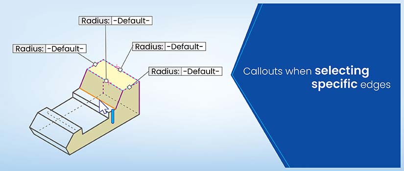
Several methods exist for modifying bend radii during the solid-to-sheet metal conversion process in SolidWorks. You can adjust individual bend radii by using callouts that appear when you select specific edges in the model. These callouts provide direct access to radius modifications without leaving the conversion interface.
The following table lists the actions and their corresponding results for modifying the bend radius of a model in SolidWorks:
| Action | Result |
|---|---|
| Select Edge | Activates bend radius callout |
| Double-click Callout | Opens radius input field |
| Enter New Value | Updates specific bend radius |
| Reset to Default | Returns to table standards |
| Apply Changes | Updates model instantly |
You can also use gauge tables to verify your bend radii conform to manufacturing standards, maintaining consistency across your design.
Setting rip edges
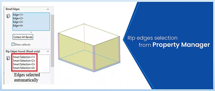
You’ll find rip-edge options under the Corner Defaults section of the PropertyManager, where you can configure specific parameters for your design.
To set rip edges, select the edges you want to separate in your model using visual selection tools. You will also have to specify the rip gap values, which determine the spacing between adjacent faces after flattening.
SolidWorks provides options for rectangular, tear, or obround relief cuts at the bend intersections.
When applying these settings, guarantee you’re working with the correct face orientations and consider manufacturing constraints.
You can adjust individual rip gaps later if needed, allowing for precise control over your sheet metal part’s final configuration.
Implementing bend allowances, relief cuts and corner treatments
You can define the bend allowance using a K-Factor or a Bend Table. The K-factor, which represents the ratio of neutral axis shift to material thickness, offers a good starting point.
For higher precision, use Bend Tables. These define the bend allowance based on the specific material, its thickness, the bend radius and the bend angle. You can access these options in the Sheet Metal feature manager or document properties. Adjusting the values for individual bends gives you fine-grained control over your model’s accuracy.
SolidWorks offers three types of bend allowances: bend deduction, bend allowance and bend table. Bend deduction subtracts a calculated value from the total flange lengths, while the bend allowance adds one. Bend tables let you reference pre-defined values.
To prevent tearing and deformation during sheet metal bending in SolidWorks, relief cuts should be incorporated. You can access relief cut options in the Sheet Metal feature manager when creating base flanges, edge flanges, or inserting bends. Common types include rectangular, circular and tear. Define the relief dimensions – depth, width and distance from the bend – to match your manufacturing needs.
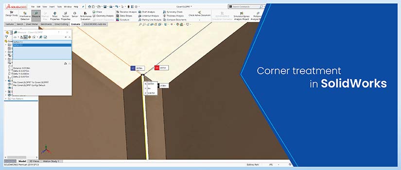
Corner treatments determine how bends intersect. Configure relief cuts in your corner defaults to manage material overlap and prevent tearing. Consider using rip gaps to separate material at corners, which often simplifies manufacturing.
The following table outlines the different types of corner treatments, their typical applications, and their key characteristics:
| Treatment Type | Application | Characteristics |
|---|---|---|
| Rectangular | Standard corners | Clean, sharp edges |
| Tear | Tight spaces | Minimal material waste |
| Obround | Stress relief | Reduces corner strain |
| Custom Relief | Complex geometry | User-defined shapes |
| No Relief | Simple bends | Material overlap |
Finalizing and validating the converted sheet metal part
When you finish the conversion, follow the steps below to finalize and validate your sheet metal part:
- Flatten the converted part: This helps ensure it unfolds correctly without overlaps or interferences.
- Inspect for conversion errors: Look for misplaced bends, incorrect material thickness, etc.
- Verify design elements: Ensure bend radii, rip gaps, relief cuts, and corner treatments match specifications and are manufacturable.
- Use the Flatten tool: Visually inspect the sheet metal flat pattern in SolidWorks, checking bends, rips, relief cuts, and rip gaps.
- Adjust Flatten settings: Fine-tune parameters like bend allowance and bend deduction for optimal accuracy.
- Perform manufacturability checks: Verify material thickness, bend radius, and relief cuts adhere to manufacturing limitations. Incorporating sheet metal detailing fabrication tips can help ensure that these details in your sheet metal part contribute to increased fabrication accuracy.
- Calculate bend allowances: Ensure these, along with flange lengths, edge distances, and overlaps, meet design intent.
- Confirm bend angles: Make sure they are achievable without causing material deformation or stress fractures.
Reduced TAT by 25% for 1,800+ shelter structure drawings in SolidWorks with 100% right first time designs

HitechDigital’s expert SolidWorks engineers delivered over 1,800 manufacturing drawings and 3D models for diverse shelter structures, reducing engineering turnaround time by 25% and design drafting iterations by 50%, ensuring 100% right-first-time designs.
Read full Case Study »Wrapping Up
When you convert solid part to sheet metal in SolidWorks, you gain access to efficient fabrication methods without sacrificing your original design goals. It is crucial to carefully check parameters like material thickness, bend allowances, and relief cuts during this conversion.
To guarantee that your part can be properly manufactured, take a moment to confirm the fixed face and bend edges.
By following a systematic conversion process and validating your results during SolidWorks sheet metal modeling, you can create manufacturable sheet metal components that maintain design intent and meet production requirements.
Convert your 3D models into ready-to-fabricate sheet metal parts.
Achieve accuracy and precision with our SolidWorks experts.


